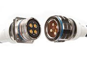
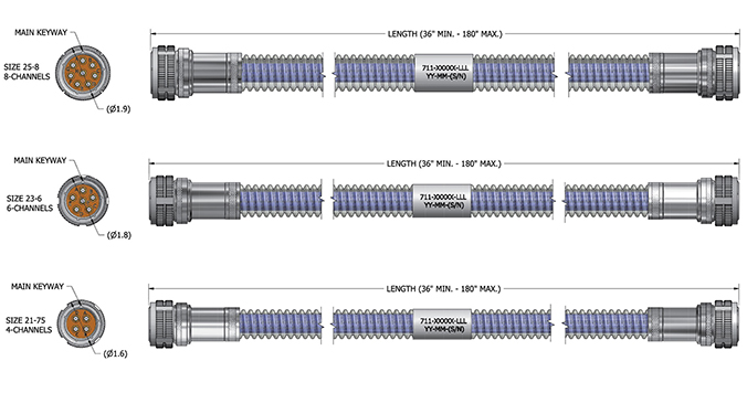
Plug to Plug with Armor
- Armored harness assemblies are typically used to connect boxes together when maximum protection of the cable is required. Various types of armor are available, from the extremely crush- and environmentally resistant rubber coated metal armors to the light weight corrugated PEEK plastic. The most popular finishes for the connectors and backshells are nickel or cadmium.
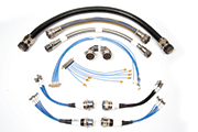
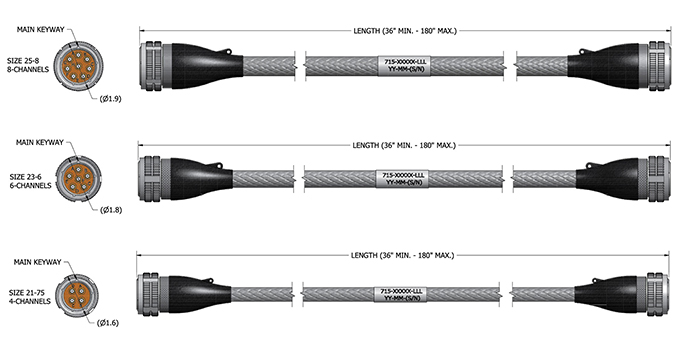
Plug to Plug with Expando Jacket
- Typically used to connect boxes or test equipment, these harness assemblies have a textile �Expando� braid over the cable assemblies to keep them contained and provide abrasion resistance. In some cases the routing convenience alone is reason to use this type of an assembly, rather than struggle with multiple individual cables. This is a lower cost option than an armored assembly, and a good choice if the operating environment is not harsh. The most popular finishes for the connectors and backshells are nickel or cadmium.
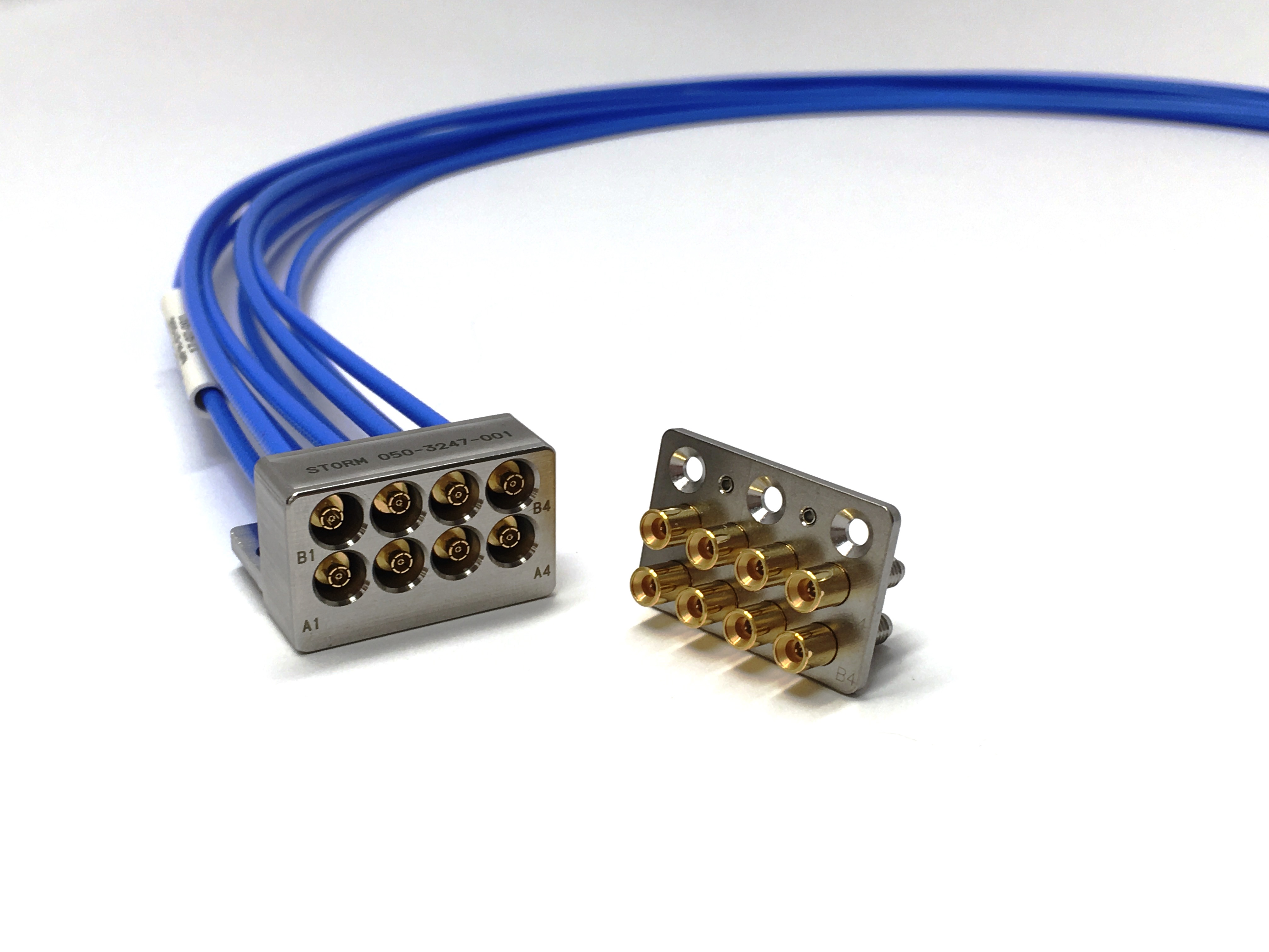
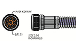
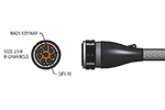
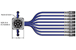
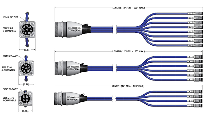
Panel Mount with Fan Out
- This harness design most commonly resides on the box or bulkhead and connects to a board or other device inside the box with discrete connections. Virtually any style connector can be placed at the fan out end; SMA, TNC, GPO, etc. It is common for the panel mount assembly to be a short run in a smaller, more flexible, higher loss cable, while the plug to plug harness used in conjunction with this has a larger diameter, lower loss cable.
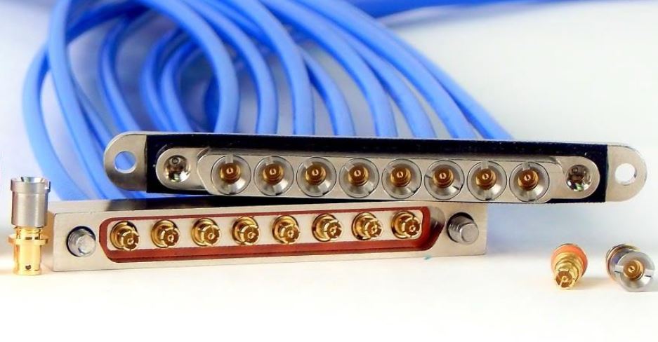
Multi-channel interconnect solutions provide the user with a number of key benefits including:
- Reduced Installation Time
- Accurate Channel Mating Conditions
- Controlled RF Performance
- Higher Density in a given space
- Fast Connect/Disconnect through keyed coupling mechanisms
Teledyne Storm has experience providing a broad range of multi-channel harness solutions for a wide variety of projects and programs. Solutions comprise harnesses ranging from basic bundled RF cable interconnects to sophisticated �fan-out� designs calling for stringent RF matching, complex housings, and multi-channel connectivity compliance.
There are ever increasing requirements for harnesses suited to higher frequency applications and utilizing smaller size coax. In line with this, it is critical to observe RF performance parameters such as shielding effectiveness and additive phase noise, and ensure RF coupling or adjacent channel coupling between contacts is minimized to acceptable levels.
Signal continuity and signal integrity must be maintained at all times in mission critical applications. In this regard, the harness connectivity solution can be viewed as the RF umbilical link between components of the platform.
Maintaining reliable RF connectivity performance while reducing contact density and maximizing real estate continues to be a challenging evolution in providing harness interconnects. Teledyne Storm's dedicated Harness Engineering Team is addressing these challenges for both today�s and tomorrow�s connectivity requirements.
We are available to engage early in your design process to guide you through the RF performance recommendations, materials selection, and environmental withstand requirements that are essential to ensure program reliability.
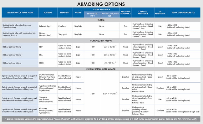
In many installations and deployments, cables are subjected to harsh environments. These environments may involve mechanical stresses on the cable, such as crushing, tension, shock, vibration, and bending. Or, the stress may come from such things as temperature extremes, chemicals, water, sand, humidity, and dust.
Since any of these forces can increase the likelihood of cable failure or degraded performance, it's important to know not only how environmental factors will impact cables but also how best to protect them.
Teledyne Storm Microwave has in-depth experience in this area and the necessary expertise to deliver both individual cable and full harness constructions capable of withstanding harsh environments while at the same time offering high levels of reliability.
Examples of some of these constructions are shown above; many variants are available, tailored to your specific application. Teledyne Storm has earned a positive reputation for risk reduction and reliability in our products by being able to adapt our knowledge of materials, support housings used in our harness product line, connector designs, and termination processing, to deliver reliable engineered solutions.
Click table to view PDF